
cutting gears on a mill manufacturer Grasping strong production capability, advanced research strength and excellent service, Shanghai cutting gears on a mill supplier create the value and bring values to all of customers.
 WhatsApp)
Not counting setup time, CNC definitely won. But the time spent on setting up easily exceeded cutting time. If you cut more than one gear, the setup time for subsequent gears drops, especially if the gears are identical. But for cutting one gear on rare occasions, the setup time is likely to far exceed the actual milling .
This leaves one more choice. This is whether a horizontal or a vertical milling machine is available. Given the choice the horizontal system is more rigid and would enable the user to cut bigger gears or cut any gear faster than would be possible on a vertical milling .
VARDEX Gear Milling tools can be used interchangeably in a wide range of applications in gear, spline, rack and sprocket manufacturing. Each tool has a different number of flutes to achieve a variety of different cutting diameters, depending on the application.
Apr 23, 2017· Broaching machine. The teeth of internal spur gears can be cut in (a) 1, 2 and 3 (b) 1 and 2 (c) 1and 3 (d) 2 and 3 56. GATE2016 (PI) A helical gear with involute tooth profile has been machined with a disctype form gear milling cutter. The helical gear has 30 teeth and a helix angle of 30o. The module of the gear milling cutter is 2.
Jun 11, 2019· See the milling of helical gears with a form cutter, a dividing head and a homebuild spiral milling attachment on an universal milling machine.
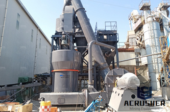
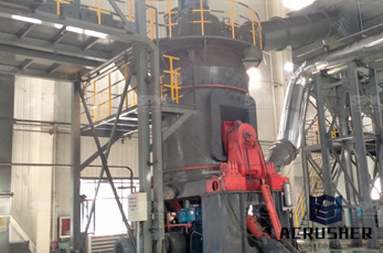
Of the various manufacturing procedures for gears milling applications are the most widely used, whether with special cutting heads and expensive special machines or with end mills on fiveaxis machining centers. Both procedures are complex and costly, but they also have a great potential for improvement. (Figure 1)
Aug 19, 2018· Milling is a cutting process where we use a cutter to remove the material from the surface of a metal or workpiece. This cutter which we use has multiple rotating cutting surfaces. Milling cutters play an important role in the milling process and they are used in several milling machines.
Also known as involute gear cutters, these tools work with a milling machine to create 14½° pressure angle spur gears. If worn, they can be sharpened and used again. To select a gear cutter, follow these steps: 1. Determine the pitch of the gear you''re cutting. Gear pitch = (No. of Teeth + 2) / OD. Round to the nearest whole number. 2.
May 05, 2010· Re: Gears and GearCutting on your mill... Post by jim rozen » Wed Apr 21, 2010 3:26 pm A stub arbor can also be used for this, to eliminate the tailstock, dog, mandrel, etc:
Procedure Of Spur Gear Cutting on Milling machine – How to Manufacture Spur Gear Gears are most important power transmission device used in mechanical assemblies. Gears are varies with respect to types, size, module, numbers of teeth on gears.
To start cutting a gear, the rotating hob is fed inward until the proper setting for tooth depth is achieved, then cutting continues until the entire gear is finished. The gear hob is a formed tooth milling cutter with helical teeth arranged like the thread on a screw. These teeth are fluted to produce the required cutting .
Jun 16, 2013· Gear cutting, Ive only done it twice. I will in the near future be making up a few gears for my American lathe. Starting with a 127 tooth gear, I will be making up a few differant tooth counts. Im determaned to cut metric threads on my lathe. I will be using a rotary table as thats what I have.
To cut bevel gears on the milling machine, you must. use special form relieved cutters. These cutters are. similar in appearance and size to those used to cut spur. gears, but they have thinner teeth. They are made to cut. gears with a face width not greater than onethird nor.

Gear cutting is a specialized form of milling, and the lathe is quite suited to this job for smaller work (6″ diameter or so) with the help of attachment. See Also : Design and Fabrication Of Gear and Spline Cutting Attachment for Lathe
Form Milling. Gear teeth can be produced by both disc and end mill type form milling cutter. Milling machines are capable of cutting practically, every type of gear by employing an universal indexing mechanism and a form cutter . The cutter has required tooth profile on it. This cutter may be operated on a vertical or horizontal type of milling ...
Continuously indexing methods of gear cutting (that is, gear hobbing, shaping, shaving, worm grinding and so forth) cannot be applied for machining highconforming gears (as well as Novikov gears). This is a consequence of that none of the tooth flanks, G and P, comprise with the generating surface of the cutting tool, T, a kind of reversibly ...
Cutting clock gears. The question I get asked most is ( How do you make the gears),or more often, where did you purchase them? For most of us our first gears ( clockmakers call them wheels) will be to a existing plan, so we will have the necessary data 1 Number of teeth 2 Module or DP of the teeth (the size) 3 The size of the blank.
Helical parts most commonly cut on the milling machine include helical gears. spiral flute milling cutters, twist drills. and helical cam grooves. When milling a helix. a universal index head is used to rotate the workpiece at the proper rate of speed while the piece is fed against the cutter.
Milling Spur Gear on Milling Machine The gear blank is mounted on a mandrel which is supported between the center of the dividing head and one more center at the other end, as shown in fig. At a time one tooth space is cut by the milling cutter, and a dividing head is used to index the job to the next required tooth space.
Dec 10, 1987· Gears and Gear Cutting for Home Machinists (Fox Chapel Publishing) Practical, HandsOn Guide to Designing and Cutting Gears Inexpensively on a Lathe or Milling Machine; Simple, NonTechnical Language
Hobbing is a gear manufacturing process in which gear teeth are generated through a series of cuts with a helical cutting tool. The hob and gear blank are rotated continuously until all teeth are cut. Hobbing is only possible for external gears. Gear hobbing advantages. Reduced total cost per gear wheel compared to HSS tools; High cutting speeds
Cutting was done by taking 23 thou at the time and pushing the tool past over the face of the raw gear by handturning the wheel of the main carriage. This was a very tedious job, about 50 times for each of the 30 valleys. For the next cut I relied on the dividerhole on the backgear of .
A whilst the gear is being cut, the milling table moves by rotating the leadscrew to the table. The rotation of the leadscrew is also used to rotate the dividing head, B the cutter has to be at the helix angle to the axis of the part whose surface is being cut. C The cutter is the same sort as used for cutting spur gears.
Sep 23, 2009· "The gear housing is a critically precise piece. The accuracy of both parts has a direct correlation to the transmission performance over the life of the motor." According Mr. Speier, the gear is mounted flat and then turned 90 degrees (or other appropriate angle) so that an end mill can cut at the best attitude to the gear profile while roughing.
WhatsApp)